


- Introduction
- While a vehicle is in motion, various forces act upon it. Driving ability, ride quality, and weight reduction to improve fuel economy are significant concerns. Testing to confirm the strength of components is critical. An evaluation test reflecting actual road conditions, generally referred to as a strength/endurance reliability test, is required to guarantee the safety of an automobile during its long service life.
Forces that act upon the vehicle can be classified into not only mechanical elements such as load, stress, pressure, and acceleration, but also into environmental elements such as temperature, humidity, and dust. In addition, road surface conditions, speed of the vehicle, and load should be considered.1) In this article, a durability test and measurement technology using a fatigue tester on actual parts are described.

1. Utilization of Fatigue Tester
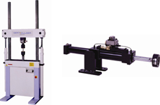
Fatigue testers owned by Kobelco Research are classified broadly into 2 types, fixed type and portable type (See Figure 1). The benefits of the latter type become apparent with the bench test, which reproduces the actual operating conditions in the laboratory, as it allows a load to be applied not only vertically or horizontally, but also from an angle to meet the load conditions. There are also many possible load capacity/stroke volume combinations, and a combination can be chosen based on the load condition. Parts are set by combining the surface table (bench), which serves as the reference plane, with general-purpose jigs.
There are a variety of means to apply load to parts, such as mechanical, electric, hydraulic, and pneumatic. Taking accuracy, general versatility, and workability into account, hydraulic equipment is the most appropriate under the present situation. The hydraulic fatigue tester, of which Kobelco Research has many, is equipped with reciprocatory cylinders in one direction (axial direction). The following is a torsion beam durability test case that was selected from many parts evaluations from the past.Figure 1Fixed-type Fatigue Tester (left) and Portable-type Fatigue Tester (right)2)
2. Torsion Beam Durability Test
Force from the road surface is input from the tires and transferred to the suspension. Due to the progressed 6 component strain gauge, which measures 3 directional forces in right-and-left, anteroposterior, and vertical directions as well as 6 forces including the moment around each axis, and the downsized in-vehicle measurement instrument, forces on the actually running vehicle can be precisely measured. The next step will be to accurately reproduce the measured forces in the bench test.
In the suspension durability evaluation, fatigue life and breaking strength are tested using an assembly or single part. Inputting the combined load improves test efficiency. There is a case to repeatedly apply load by focusing on only one direction, such as vertical, right-and-left, or the anteroposterior direction.
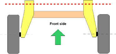
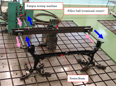
An automobile suspension layout is shown in Figure 2. The part mounted in the center is called a “torsion beam.” A test to repeatedly apply load to the torsion beam in the horizontal direction is the endurance test shown in Figure 3.
While the vehicle is in motion, forces as a result of the roughness of the road act in the vertical direction. To reproduce the situation, relative displacement is given to both the left and right wheels (the areas where the tires are installed) so as to check the durable strength of the torsion beam. It is considered that 2 sets of load equipment (the fatigue tester) are required because both left and right wheels need to be loaded. By using the jig with the rotational center, should one side be pulled, the other side would be pushed. Adopting this method makes possible the rendering of relative displacement with only one fatigue tester.
-
Figure 2Automobile Suspension Layout 3)
-
Figure 3Torsion Beam Endurance Test Case
In the durability test, it is necessary to clarify the stress generation status, presence and location of any cracks, and then to feedback such information to the design. The strain gauge method is a widely known method to measure stress applied to parts. It is easily attached and enables accurate measurement, but a drawback of this method is that it merely measures stress at a single point, so a technique that measures planar stress distribution of complicated assemblies is needed. One of the techniques used is infrared thermography, which applies the phenomenon known as “thermoelastic effect”, temperature change as a result of elastic variation and volume change. When an object is compressed, it generates heat, and when pulled upon, it absorbs heat. Therefore, by using the thermoelastic effect in combination with infrared thermography, stress distribution measurements become possible. It is possible to realize accurate measurements of simply shaped objects like a test piece. Stress measurement of single parts or assemblies possessing complicated shapes has begun.
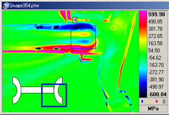
- Figure 4 shows the stress contour when a relative displacement in vertical direction is input to the torsion beam. Areas shown in red and blue are highly-stressed, which intercorrelates with the actual part. The angle of the infrared camera and distance from the measurement target are the deciding factors for optimizing monitoring of parts movement, etc. If the stress distribution can be established, quantitative numerical values need to be calculated. Actually, stress value is calculated, but its accuracy needs to be verified. In comparison with values of the strain gauge, differences were more than double. Therefore, possible causes for such differences were identified, interference (light and dust) was removed, and the frequency was varied while considering the effect of thermal diffusion. It was confirmed that the value approached the strain gauge value when the frequency was increased, and that a frequency of around 10Hz resulted in considerably accurate measurement. It is hoped that through the application of correction software to compensate for locations where bending and torsion occur further accurate measurements will become possible in any area.
-
Figure 4Graphic of Stress Contour
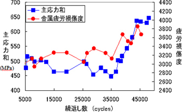
- Once the strain distribution is understood, presence or absence of cracks can be confirmed by tracking the change. In principle, cracks are checked when the parts are assembled. Therefore, the solvent removable penetrant inspection is effective in the present circumstances, but the measurement using infrared thermography is being continued to increase work efficiency and realize high value-added work. Not detecting cracks, but the method to determine cracks based on the stress field at the crack edge or the surrounding stress change condition is being pursued. The process of stress distribution change as the cracking spreads can be confirmed. Also, the relationship with metal fatigue damage level has been investigated. An example is shown in Figure 5. Metal fatigue damage level was measured with a portable magnetic fatigue evaluation device, which enables viewing of fatigue damage level through the change in magnetic characteristic values measured every certain number of cycles. Both principal stress sum measured with the infrared thermography and metal fatigue damage level at over 35,000 cycles tend to increase, which becomes an effective method for crack flaw inspection. (The initial crack was confirmed at 40,000 cycles.) The goal is to make a system able to forecast fatigue life through the application of this technique to measure different materials and shapes.
-
Figure 5Transition of Principal Stress Sum and Metal Fatigue Damage Level
- Conclusion
- In this article, durability test and measurement technology for automobile parts were presented. Reproducing the actual running result in the bench test is the primary target, and doing so will help automobile manufacturers in shortening their development period. In addition to simple measurements, improving measurement accuracy, shortening measuring time, the study result derived from the measured data are beneficial items to be proposed. If fatigue life estimation can be established through the results of the experiments, measurements, and analysis, it will become information that can be reflected in designing automobile parts, which will be a great contribution to automobile manufacturing.
- References
- 1) Automobile Technology Handbook 7- Testing and Evaluation (Vehicle) No. 2, P. 63, Society of Automotive Engineers of Japan, 2006
- 2) Shimadzu Corporation’s Website: http://www.shimadzu.co.jp/test/products/mtrl02/index.html
Examination & research example
- Automotive
- Automotive Durability Evaluation Technology ~ 4-Poster Testing~
- Automotive Durability Evaluation Technology ~Durability Test and Measurement Technology ~
- Evaluation Technologies on High Strength Steel Sheet Atmospherefor Automobiles
- Safety Evaluation Test of On-board Lithium-ion Battery
- Techniques for Evaluation of Applicability of Biofuels