


- Introduction
-
Through the use of durability evaluation technologies and other technologies for materials evaluation, processes, various simulations, and visualization through measurement, Kobelco Research is focused on becoming a comprehensive automotive testing company. As part of this effort, in May 2008 the company began use of a 4-poster automotive test system, a system for testing automobile durability. The 4-poster test system is a durability testing system which simulates harsh road conditions and other such operating environments. Its main use is to check for welding cracks in the body.
This paper describes full-scale vehicle durability testing and simulation technologies using this 4-poster test system.

1. 4-poster test system (4-wheel road simulator)
The durability and reliability development process for automobile body and chassis components entails both operational and stationary durability experiments to assess and measure loads while accounting for road conditions and applications for use. Stationary durability testing allows more stable shaking than operational durability experiments. Consequently, due to improved precision and shorter durability testing cycles, the use of stationary durability testing is increasing.
Stationary testing systems are referred to generally as road simulators and include such systems as 4-wheel road simulators which take vibratory input from tires, multi-axis road simulators with 4 or 6 degrees of freedom which vibrate spindles secured directly to a vibrator, and multi-axis vibrating tables where the vehicle body or driveshaft is secured for testing. Each vibration technique evaluates different points.1)
Kobelco Research currently has available an environment capable of full-scale vehicle testing with a 4-wheel road simulator. This system is used for general, full-scale vehicle development by various automotive firms.
Table 1 shows the performance of the system during SUV-class testing. Photograph 1 shows real-time vibratory conditions.
-
Table 14-poster test system specifications (for SUV class)
Hydraulic Shaker Load 50kN Displacement 300mmP-P Speed 4.5m/s0-P Acceleration 21G0-P Spring Top Maximum Static Mass 1300kg Spring Bottom Maximum Mass 100kg Piston Diameter 80mm Wheel Plate Size 20inch (508mm) Maximum Vibration Frequency 100Hz Shifter Tread 1160mm-1750mm Wheel Base 2000mm-3500mm Hydraulic Supply Source Discharge Rate 681litter/min -
Photograph 1Shaking by 4-poster test system
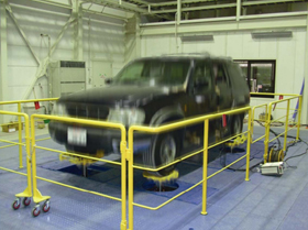
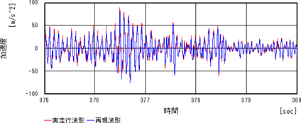
Reproduction of field measured operating waveforms in a 4-wheel road simulator involves measurement of the transmission characteristics of sensors and vibrators attached to the vehicle body and use of feed-forward control based on these measurements for iterative resolution of error from target waveforms. Figures 1 and 2 show results for a comparison of field measured operating waveforms and reproduced waveforms. The comparison shows that there is no difference in phase, and amplitudes also nearly match.
- References
- 1) Toshiaki Nakamaru: Society of Automotive Engineers of Japan (Durability Test with a Road Simulator for Body and Chassis Parts Durability Development) Vol. 59 (2005) No. 7, pp. 89-94.
Figure 1Comparison of field-measured operating waveform and reproduced waveform
(below spring / acceleration / front left side)

Figure 2Comparison of field-measured operating waveform and reproduced waveform
(below spring / acceleration / front left side, enlarged)
The system in use at present is capable of shaking vehicle classes from light automobiles to pickup trucks and provides an environment capable of testing most passenger vehicles operated in Japan. It is also notable for its ability to test two-wheel vehicles, trucks, and other specialty vehicles in a variety of full-scale vehicle tests.
The system also has measuring technology for automobile vibration in actual operation and is capable of performing complete testing.
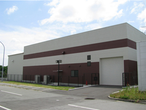
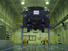
A new facility was constructed for putting the current 4-poster test system into place. Photograph 2 shows the exterior of the testing facility. The testing facility is isothermically controlled to a temperature of 23°C ± 5°C, and the entire building is covered with gas concrete to cancel noise. The entire 4-poster test system itself is also supported by a floating base structure which minimizes vibration produced, and the structure used does not propagate vibration externally. The building structure was designed with confidentiality in mind. The testing facility also provides an environment for efficient testing, with equipment such as ground embedded maintenance lifts (shown in Photograph 3) enabling linear movement from the 4-poster test system, and specialized welding equipment for repair.
Photograph 2Testing facility exterior (Large-Scale Vibration Experiment Section)
Photograph 3Inspection lift
2. Suspension mechanism analysis
Operating simulation of 4-poster testing performed before actual testing allows selection of measurement points in 4-poster testing and provides an understanding of quantitative stress at non-measured points. Performance of operating simulation is crucial for (1) modeling of areas where doors and glass are attached to the body, and (2) development of modeling technologies to incorporate the dynamic characteristics of various suspension components such as springs, shock absorbers, bushings, and torsion beams. Modeling of suspension components is discussed below. To understand the dynamic characteristics of components, as shown in Photograph 4, a gate-shaped fixture was fabricated, and 1 post of the 4-poster tester is used for dynamic characteristics testing of individual components in order to understand frequency dependence and displacement dependence.
The dynamic characteristics of springs, shock absorbers, bushings, and other such components must first be identified in order to establish applicable frequency and amplitude ranges. In this process, measurement data from 4-poster testing are first used to understand the actual prevailing frequency range and suspension stroke characteristics at the time of the test.
In the test vehicle analyzed in this case, it was found that the greatest frequency peaks were present below the springs at 5-25 Hz and above the springs at 2 Hz, and that components of 20 Hz or less could be an acceptable representation of the behavior of the vehicle body as a system. For the suspension stroke, relative displacement was found to be approximately ± 50 mm at maximum and approximately ± 25 mm on average, and relative velocity was approximately ± 1 m/s.
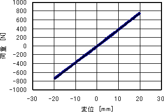
The displacement load plot test results shown in Figure 3 demonstrated that the coil springs used in the suspension had characteristics ideal for a spring, as predicted, with very high linearity, practically negligible attenuation, and no displacement dependence.
Photograph 4Gate frame (for 1-poster shaking)
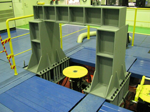
Figure 3Displacement-load plot
The effect of rubber bushings used principally as suspension part couplings also cannot be ignored. Because rubber bushings have a non-linearity unique to rubber and other attenuation characteristics represented by a loss coefficient, bushing units were subject to vibratory experiments in which the dynamic characteristics of each bushing were investigated. The spring constant and loss coefficient of bushings were found to be nearly constant at all frequencies, and other dynamic characteristics showed properties of ordinary rubber. In loss coefficient type damping, attenuation is a force proportional to displacement of an imaginary part, which can be expressed easily in frequency response analysis, but in time history response analyses such as the current mechanism analysis, conventional methods cannot be used to consider imaginary parts. Consequently, a shift was first made to modeling an equivalent, proportionate attenuation at the prevailing frequency (2-3 Hz).
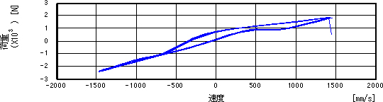
Shock absorbers make use of oil or another viscous fluid to serve as a damping element, but from perception based on ride, for example, they were anticipated to have non-linear characteristics, and experiments were performed with varying frequency/velocity amplitude. As shown in Figure 4, rear absorbers demonstrated nearly linear characteristics. However, as shown in Figure 5, front absorbers demonstrated non-linear characteristics. Front absorbers also showed hysteretic characteristics, suggesting that the spring characteristics of the absorbers or inertial characteristics of the fluid in the damper may be substantial. A skeleton curve was thus derived from the curve to express non-linear attenuation characteristics as mechanism analysis data.
Figure 4Rear absorber velocity-load curve
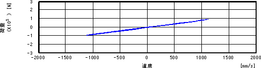
Figure 5Front absorber velocity-load curve
In an automobile suspension, elements such as torsion beams and stabilizers are used to restrain relative displacement of the left and right tires elastically. This is essentially a use of the torsional rigidity of the beam structure, but because this shape is an open cross-sectional structure, torsional rigidity must be expressed with good precision reflecting this structure. And because results for torsional rigidity and the center of rotation determined from the FEM model created were found to match closely with those calculated by a theoretical formula for the torsional rigidity of the open cross-sectional structure, the values now used are those obtained from the theoretical formula.
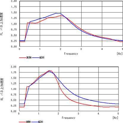
As described above, experimental techniques and identification techniques were developed to determine the dynamic characteristics of individual parts of suspension structural members. On this basis, a mechanism analysis model like that shown in Figure 6 was constructed, and a comparison was made between test results and mechanism analysis results for excitation of a common mode (housing), as in 4-poster shaking. As shown in Figure 7, these results showed quantitative agreement for frequencies representing peaks and peak values. Though the results from this analysis are limited to certain vehicle types, future work will pursue test analysis of other suspension types and experimental evaluation of other vehicle types to generalize the findings for technologies acquired in different cases and thus advance this technology,. Work also continues to create evaluation and analysis technologies in still higher frequency ranges focusing not only on strength, but also ride feel, control stability, and road and other vibratory noise.
Figure 6Suspension mechanism analysis model
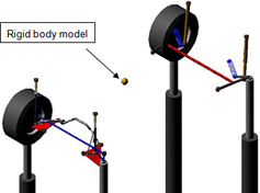
Figure 7Comparison of test measurement results and analysis results
(Left: front left-side, above-spring acceleration, Right: rear left-side above-spring acceleration)
- Conclusion
- This paper discusses a 4-poster test system and the creation of analytical technologies and techniques used in the system. Through further durability testing in virtual environments, and through additional detailed evaluations of body and in-vehicle components after durability testing, Kobelco Research is focused on creating technologies that make the company a complete and comprehensive automotive testing firm.
Examination & research example
- Automotive
- Automotive Durability Evaluation Technology ~ 4-Poster Testing~
- Automotive Durability Evaluation Technology ~Durability Test and Measurement Technology ~
- Evaluation Technologies on High Strength Steel Sheet Atmospherefor Automobiles
- Safety Evaluation Test of On-board Lithium-ion Battery
- Techniques for Evaluation of Applicability of Biofuels