


- Introduction
-
Safety Evaluation Test of On-board Lithium-ion Battery
Lithium-ion batteries are widespread for portable devices since they were commercialized in 1990s. In recent years, development of lithium-ion batteries for automobiles is rapidly promoted and they have been developed in size, focusing on their high energy density. As securement of durability and reliability is important for practical application of lithium-ion batteries, research and development for enhancing its life, charging/discharging efficiency and safety have been promoted. As part of the research and development, evaluation of battery material, clarification of deterioration mechanism, observation inside the batteries, safety evaluation and charging/discharging performance evaluation assuming even erroneous usage, and the simulation of these evaluations by the numerical analysis are becoming important.
Regarding the safety evaluation of the lithium-ion batteries, although the lithium-ion batteries for portable devices have been already specified in JIS*1), those for EV or HEV applications are not included in the JIS standard. In the safety evaluation of lithium-ion batteries, the nail penetration test simulating the possible internal short-circuit for batteries and the United Nations (UN) recommendation test for the safety confirmation test at transportation*2) are applicable. Accordingly, approach and handling of our company for these safety evaluation tests are introduced.

1. Internal short-circuit test
- 1.1 Design of test equipment
-
-
Lithium-ion batteries discharge the accumulated electric energy in a short time, if internal short circuit occurred for some reasons such as mixing-in of foreign substances or collision damage. If internal short circuit occurred in a cylindrical cell with the standard 18650 size (18 φ × 65 mm, average voltage of 3.7 V, capacity of 2 Ah), energy of max. 27 kJ is discharged, and it can result heat generation, liquid leakage, smoking, burst, ignition, etc. In order to evaluate an abnormal event due to internal short circuit, the nail penetration test is applied in which a cell is penetrated by a conductive nail with the predetermined speed, and the voltage, temperature, gas generation, etc. are measured. As a nail penetrates, short circuit occurs between a positive electrode and a negative electrode while the nail acts as a conductor and Joule heat is generated (Figure 1). Owing to the rapidly generated heat, decomposition of electrodes, dissolution of solvent, etc. occur, and there is a risk of abrupt gas generation. Therefore, sufficient countermeasures are necessary for executing the test itself safely.
-
Figure 1Heat generation phenomenon due to internal short circuit
-
The nail penetration testing machine as shown in Figure 2 was devised in order to apply to a large-scale cell*3). By setting the lithium-ion battery into the nail penetration test container and substituting inside the container with inert gas, it is possible to perform the test without generating ignition by generated gas. The sliding part with high airtightness so as to prevent gas leakage from the nail penetration part or suctioning of air, and the buffer tank to rapidly collect the generated gas were designed and manufactured. Since all the generated gas can be collected, it is possible to evaluate the thermal decomposition process and generation of minute amounts of hazardous gas. Observation windows are provided in two directions on the container to facilitate its internal observation. Further, measurement of variation in voltage and temperature of the battery due to internal short circuit was made possible via the airtight flange. As a result of various safety countermeasures, tests of the large-scale electric cell became possible.
-
Figure 2Heat generation phenomenon due to internal short circuit
-
- 1-2. Trail test results
-
A nail penetration test was executed using a commercially-supplied lithium-ion cell. The test conditions are shown in Table 1.
As the result of the test, the obtained data such as cell voltage drop, cell temperature rise and so on, due to the penetration of the nail are shown in Figure 3. Voltage drop started about 0.06 min after nail’s penetration into the cell, and temperature rise on the surface of cell started at the same time. It has been shown that internal short circuit occurred due to penetration of the nail between electrodes and then Joule heat was generated. The voltage became almost zero about 0.2 min after the nail was stuck, and surface temperature of the cell reached approx. 380oC at maximum, after about 0.6 min. A part of video recording through an observation window is shown in Figure 4. It was observed that the laminate film of the cell package has been expanded due to nail’s penetration and gas has been generated cell inside. As the result of analysis of the generated gas by collecting the all amount of evolved gas by means of argon ventilation, it has been confirmed that about 10 liters of the gas containing mainly CO2 and CO, with additional C2H4, CH4, C3H8, C2H6, and H2 gases and the gas with the solvent component have been generated.Table 1Nail penetration test condition
Tested cell Cell: Laminate type cell
Charging: CC-CV modeNail penetration condition Nail: 5 mmΦ, 10 mm/s Atmosphere Argon atmosphere
-
Figure 3Result of the nail penetration test
-
Figure 4Result of observation about the nail stick test
- (a) Just before the nail is stuck
- (b) The nail is penetrating by several mm.
- (c) The nail has penetrated and the laminate has been expanded due to the generated internal gas.
- (d) Gas has blown out from a part of the laminate and has been filled in the container.
2. UN recommendation test
- 2-1. Contents of the test
The UN recommendation test was specified as the UN’s regulative recommendation with regard to the transportation of hazardous substances, as the method of evaluating safety of batteries by assuming various events during transportation. This recommendation is the transportation standard of hazardous substances in the overland, marine, as well as air transportation modes, and it has become the standard for international transportation of lithium batteries.
The targeted batteries are all lithium batteries, the electric cell and assembled batteries of the lithium-ion batteries. Regarding the test method, it is specified to execute eight items of the test, from T1 to T8. As for the large-scale electric cell which is for EV or HEV applications, the seven items except for the T7 targeting assembled batteries are specified (Table 2). Here, the large-scale electric cell denotes the lithium-metal electric cell beyond the lithium content of 12 g, and the lithium-ion electric cell beyond the watt-hour rating value of 150 Wh.Table 2UN recommendation test for large-scale electric cells
Item Purpose Test method Requirements T1: Altitude simulation Assuming the low pressure condition during air transportation To be stored in the decompressed atmosphere at the pressure of 11.6 kPa or below, with ambient temperature of 20 ± 5oC, for at least 6 hrs. • There shall be no mass decrease, liquid leakage, valve opening, burst, breakage, or ignition.
• Open-circuit voltage shall be held to 90% or more in comparison to that of before the test.T2: Temperature test Evaluating sealing performance of the battery and internal electrical connection by means of rapid and extreme temperature variation Repeat the test cycle of 75oC × 12 hrs or over → −40oC × 12 hrs or over, with the interval of 30 min or less between the test temperatures by 10 times. After that, store it under the ambient temperature and for the period of 20oC × 24 hrs. T3: Vibration Assuming vibration during transportation Repeat the test cycle in the frequency of 7 Hz → 200 Hz → 7 Hz (1 G → 8 G → 1 G)/set for 15 min. Test time: 15 min × 12 set × 3-axis directions = 9 h T4: Shock Assuming shock during transportation Apply the half-sine wave acceleration with the peak of 50 G and duration of 11 msec. Apply 18 shocks in total, on respective 3 axes in the positive and negative direction each, and three times each. T5: External short circuit Assuming external short circuit Make a short-circuited state with the external resistance of less than 0.1 Ω at the temperature of 55oC. After holding the short-circuited state for 1 hr or more, observe it for 6 hrs. • The external temperature shall not exceed 170oC.
• There shall be no burst, ignition within 6 hrs after the test.T6: Collision Assuming collision by a heavy load Put a round bar with 15.8 mm diameter on the battery and drop the weight of 9.1 kg from the height of 61 cm, on the bar. T7: Overcharge Durability evaluation for the overcharged state of assembled batteries Charge the battery with the current of twice the maximum continuous charging current recommended by the maker. The minimum voltage of the test is specified by the recommended charging voltage. • There shall be no burst, ignition within 7 days after the test. T8: Forced discharge Durability evaluation for the forced discharge state Perform forced discharge during the time equivalent to the value of dividing the rated capacity by the initial test current, which is equal to the maximum charge current specified by the maker. - *1: T1 to T5: Tests shall be performed continuously with the same battery, and shall be performed using 20 pcs of electric cells in total, with 10 pcs in a fully charged state and 10 pcs in a fully discharged state.
T6: (1) 5 pcs for the initial cycle (50% charged state), (2) 5 pcs for the cycle of 50 times (fully discharged state); T8: (1) 10 pcs for the initial cycle (discharged battery), (2) 10 pcs for the cycle of 50 times (fully discharged state) - *2: T6 and T8 are only applicable to electric cells. T7 is only applicable to assembled batteries. T1 to T5 are applicable to electric cells and assembled batteries.
- *1: T1 to T5: Tests shall be performed continuously with the same battery, and shall be performed using 20 pcs of electric cells in total, with 10 pcs in a fully charged state and 10 pcs in a fully discharged state.
- 2-2. Provision/Upgrading of test equipment
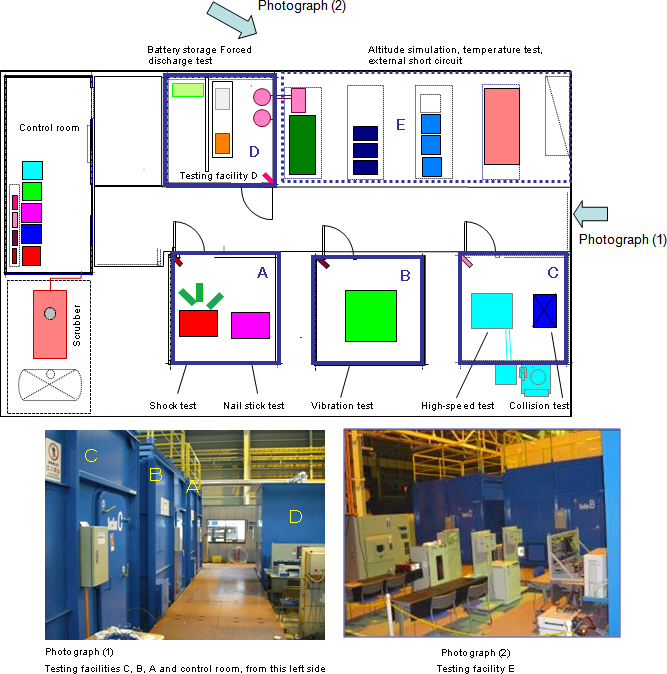
In order to execute the UN recommendation test for the target of large-size lithium-ion electric cells for EV or HEV applications, the test equipment and safety equipment suitable for each test are investigated and provided/upgraded. In order to minimize the influence of thermal runaway, blowout of gas, ignition, etc. due to unexpected battery trouble during the test, each set of equipment was installed in the single cubic type testing facility for the vibration test, shock test, collision test, forced discharge test, and storage of the battery after the tests. Each test facility is provided with the monitor in addition to the necessary ventilation equipment, and thus, remote confirmation about soundness of the battery during the test and storage is made possible. The arrangement of the test facilities is shown in Fig.5. In any test and at storage after tests, the battery voltage, temperature on the battery surface, etc. are monitored and evaluation is performed by confirming the presence or absence of abnormality such as burst, ignition and liquid leakage.
Figure 5Test facilities for the UN recommendation
- Conclusion
- Due to recent tendency of the energy situation, batteries have been drawing attention in a manner extreme enough to be labeled as “Batteries are the rice of industries.” Although batteries are considered as the key device of the low-carbon society, when they are used for EV or HEV, it is deemed as indispensable to secure reliability and safety requested for automobiles. As one of the evaluation technologies for that purpose, various safety countermeasures have been devised, and the nail penetration test of the large-scale electric cells for automobile applications as well as the UN recommendation test have been put into practical applications. We are aiming for contributing to the research and development of safe batteries, by further enriching the charging/discharging test equipment, assembled battery test equipment, etc. from now on.
(Collective writing: Hirofumi Totsuka, Engineering Department, Electronics Division/Norihisa Yokoyama, Technical Office, Takasago Plant)
- References
- *1) • JIS C8712 (2006): Safety requirements for portable sealed secondary cells, and batteries made from them, for use in portable applications
• JIS C8713 (2006): Secondary cells and batteries containing alkaline or other non-acid electrolytes - Mechanical tests for sealed portable secondary cells and batteries
• JIS C8714 (2007): Safety tests for portable lithium ion secondary cells and batteries for use in portable electronic applications
• JIS D5305-1 (2007): Electric road vehicles - Safety specifications - Part 1: Traction battery
• JIS D5305-2 (2007): Electric road vehicles - Safety specifications - Part 2: Functional safety means and protection against failures
• JIS D5305-3 (2007): Electric road vehicles - Safety specifications – Part 3: Protection of persons against electric hazards - *2) Guidebook for Transportation of the Lithium-metal Battery and the Lithium-ion Battery, Battery Association of Japan, 4th version, April 2009
- *3) Patent application JP2009-148003: Safety evaluation test method and its test equipment; Kobelco Research Institute, Inc., Tsuyoshi Imakita, Hirofumi Totsuka, Norihisa Yokoyama
- *1) • JIS C8712 (2006): Safety requirements for portable sealed secondary cells, and batteries made from them, for use in portable applications
Examination & research example
- Automotive
- Automotive Durability Evaluation Technology ~ 4-Poster Testing~
- Automotive Durability Evaluation Technology ~Durability Test and Measurement Technology ~
- Evaluation Technologies on High Strength Steel Sheet Atmospherefor Automobiles
- Safety Evaluation Test of On-board Lithium-ion Battery
- Techniques for Evaluation of Applicability of Biofuels