


- Introduction
- Improvement of fuel consumption characteristics (reduction of CO2 emission) and improvement of collision safety are the social responsibility requested to automobiles. To these tasks, the meaningful directions of response are weight reduction of car bodies, and improvement as well as innovation of engine performance as represented by the hybrid system. In recent years, use of the high strength steel plate (High-Tensile Steel) is rapidly increasing as the means of carbody weight reduction, and in some types of automobiles, it is used more than 50% of the car body. Here, we introduce recent trend of the high-tensile steel, the feature requested at use, and its evaluation technologies.
 |
|---|
1. Recent high strength steel sheet for automobiles (high-tensile steel)
Since it was shown that weight reduction of car bodies by 25% can be achieved in the ULSAB (Ultra Light Steel Auto Body) project*1) implemented by IISI (International Iron and Steel Institute) in 1994, enlargement of the locations where high-tensile steel is applied, as well as application of the steel sheet with stronger strength have been promoted at an accelerated pace.
The car components where steel sheets are used consist of the panel components represented by outer panels, underbody components where hot rolled steel is mainly used, structural components forming the frame of car bodies, and reinforcing components for securing safety of crew. Excellent rigidity and collision energy absorption capacity are requested for the structural components and impact resistance characteristics are requested for the reinforcing components.
Although various kinds of steel sheets for automobiles have been developed as shown in Fig.1, elongation decreases as the strength increases, in general. However, in recent years, the steel sheets with comparatively high strength and large elongation, called AHSS (Advanced High Strength Steel) have been drawing attention. DP-CP is abbreviation of the "Dual Phase-Complex Phase." DP steel has the controlled structure in which approx. 10 to 30% of martensite is dispersed in the ferrite matrix to achieve large elongation as well as the low yield ratio, and it is widely used for 590 MPa and 780 MPa class steel sheets. CP steel has the multiphase structure that further contains bainite, aiming for higher strength. TRIP (Transformation Induced Plasticity) steel has introduced about 10% of retained austenite, and it is used for 590 MPa and 780 MPa class steel sheets as the steel sheets showing larger elongation. On the other hand, the steel in which the ratio of martensite in DP steel has been further increased, or the steel sheet with 100% of martensite (MART; Martensite) is used for reinforcing members as the ultra high-tensile steel exceeding the 980 MPa class, for responding to the trend of higher strength. Among those, the steel sheet containing retained austenite has been developed.
Moreover, for the 1,470 MPa class, there are problems such as decrease of elongation, lowering of the press forming limit, and increase of spring back. Therefore, the hot stamping technology (also called die quench, or hot press) has been put into practical use. In this technology, the 0.22% C-1.2% Mn-Cr-Ti-B steel is heated in the austenite range, then formed by press at high temperature, and put into martensitic transformation in the press dies to obtain strength. This technology was fully adopted in Europe in the 1990s and has been drawing attention also in Japan recently. The door impact beam has been utilized in which the steel with similar composition has been processed in cold forming, and then put into martensitic transformation by quenching treatment. The components which have been quenched and strengthened at only necessary positions have been also put into practical use.
Although not shown in Fig.1, TWIP (Twinning Induced Plasticity) steel that shows very large elongation of about 70% at 800 to 1,000 MPa has been developed recently*3) *4). The feature of this steel sheet consists in that the basic phase is of the austenite structure, the bicrystal is generated at the place where deformation has progressed, then the place is hardened and suppresses generation of cracks, and it shows very large uniform elongation. Research and the study for practical use of this material have been performed mainly in Europe. However, some problems have been pointed out such as requiring Mn of 20% or more to stabilize austenite, high cost, and delayed fracture characteristics. Further, the low density steel has been also proposed which has similar composition and contains Aluminum of about 6%*4). On the other hand, it has been reported that when a tensile test is carried out for TRIP steel containing 0.4% C at the warm temperature of 150 °C, the equivalent strength and elongation to those of TWIP steel can be obtained*5). In order to be used as the steel sheet for automobiles, there are still many tasks to be studied, such as adjustment of composition and warm working method. However, it draws attention as the future high-tensile steel for automobiles and processing technology, as same as TWIP steel.
Figure 1Relationship between strength and elongation for various steel sheets (Data published by IISI)*2)
- *1) ULSAB Electrics Report: The ULSAB Consortium, (1998)
- *2) IISI AUTOCO Report: www.worldautosteel.org
- *3) J.Kiese: International Symposium on Niobium Microalloyed Steel Sheet for Automotive Application, (2006), p89
- *4) G.Frommeyer et al.: ISIJ.Int.43, (2003), p438
- *5) M.Mukherjee et al.: ISIJ.Int.46, (2006), p316
2. Case example of structure observation
As described in the previous clause, DP steel, TRIP steel, or martensite steel sheets are drawing attention as AHSS. In these steel sheets, not only elongation, but also hole-expanding properties and bendability become also important characteristics depending on the location to be used. In order to control these characteristics, it is important to control martensite, austenite, cementite, etc., and it is requested to precisely grasp the configuration of these phases including the dispersed state. Moreover, in order to understand the deformation behavior of respective steel, it is also necessary to know how each phase is deforming during plastic deformation.
Fig.2 shows the observed result of DP steel's structure by means of the ASB detector (Angle Selective Backscattered Electron Detector) mounted on the SEM-EBSD (Scanning Electron Microscope-Electron Back Scatter Diffraction) and on the FE-SEM (Field Emission-Scanning Electron Microscope). In EBSD, the dispersed state of the ferrite phase shown in red, the austenite phase shown in green and the martensite phase shown in black which is not identified due to high dislocation density is observed. On the other hand, in ASB, discrimination of the phases is possible from the condition of contrast. In ASB, the image is obtained in which the channeling contrast (crystal orientation information) has been reflected, by detecting the ultra low-angle scattered reflection electron. Owing to this, the knowledge of orientation difference, etc. caused by sub-grains in crystal grains and plastic strain in micro regions can be comparatively simply obtained. By taking advantage of this feature, it is utilized for short-time observation of orientation change from wide regions to micro regions, and observation of dislocated substructure such as sub-grains, etc.
Figure 2Example of observation for DP steel by means of EBSD and ASB
Figure 3*6) shows an example of observation about the change in structure involved in the deformation of DP steel by means of the SEM-EBSD. The case a) shows the base material, and b) shows the orientation mapping by the OIM (Orientation Imaging Microscopy) image after tensile deformation of 26% was applied to it. The black regions dispersed in a) are martensite. In the case of b), the position is also represented in black where the Kikuchi line became unclear due to generation of local large strain by deformation, in addition to martensite. The graphs below the each figure are the profiles in which the difference of orientation is measured along the lateral line at the center of the OIM image, and the red lines show the difference of orientation between adjacent measurement distances (1 step corresponds to 0.1 μm), and the blue lines show the difference of orientation between the point of origin and the measurement points. Further, in order to clarify the correspondence of locations at the initial state (a) and at the state after deformation (b), the corresponding regions are shown by the symbols A to I. In the case of a), each crystal grain is shown in a single color (orientation). However, in the case of b), the gradation has appeared inside the grains, and it is found that difference of orientation has appeared in each crystal grain due to deformation. Accordingly, in the orientation difference profiles, inside the grains is flat and there is almost no difference of orientation except for the difference of orientation at the grain boundaries, in the case of a). But, in the case of b), the profile inside the grains shows the saw teeth form and there are variations of orientation in small cycles. Therefore, it is found that martensite has produced the increase in the orientation difference of adjacent ferrite. Through such observation, it is possible to know the deformed state of ferrite generated in the course of deformation of DP steel and the influence exerted by martensite.
Figure 3Example of observation about the orientation change before and after the deformation by means of EBSD for DP steel*6)
- *6) Ohtani, et al.: Tetsu-to-Hagane, Vol.95 (2009), p.620
Along with the recent development of higher strength, the steel sheets with the tempered martensite structure are drawing attention. In that case, it is requested to simply and easily observe the dispersed state of cementite produced by tempering. Fig.4 shows the result of observation about the generation state of voids after tensile deformation with regard to the material which was tempered at 600°C after quenching from austenite, at 20,000 powers, using the FE-SEM. It is observed that a number of fine cementite blocks with the submicron size (approx. 100 nm) have deposited at the grain boundaries, and voids have been generated from those starting points. In the case of this structure photograph, etching was performed with picral in order to observe fine cementite. Although the finer cementite than this cannot be shown by the reason of paper space, the acicular fine cementite deposited by low-temperature tempering at approx. 250°C can also be observed with this method.
In TRIP steel, confirmation of the amount or dispersed state of retained austenite is important. Measurement of retained austenite can be generally obtained by X-ray diffraction method. Measurement of the amount of retained austenite at the specific region, for example, a fine region of the punched hole part is also requested. In that case, it becomes possible by using the fine X-ray diffraction equipment that can narrow down the beam diameter to about 100 μmΦ. In the case of measurement by X-ray, only the information of certain specific measuring surface can be detected. However, if the saturated magnetization method*7) is used, the amount of retained austenite in the whole range of 3.6 × 4 × 30 mm can be measured. In the case of a steel sheet with the thickness of about 1 mm, it becomes possible to grasp the amount of retained austenite for total sheet thickness by the measurement of its stack. Moreover, the dispersed state of retained austenite can be observed using the SEM-EBSD, as shown in Fig.2. We are providing the suitable analysis means in accordance with purposes.
Figure 4The dispersed state of cementite in the tempered martensite and the generation state of voids after tensile test
3. Evaluation of utilization technologies
- 3-1. Evaluation of formability
- When evaluating the steel sheets for automobiles, the formability test is requested first. Various formability evaluations such as the measurements of FLD (Forming Limit Diagram), the Ericksen test, the conical cup test, the bending test specified in JIS, and the hole expansion test specified by the Japan Iron and Steel Federation Standard (JISF) are carried out using a 500 kN compact-single press machine. In addition, a large-scale formability evaluation using a 10,000 kN large-size press was done. Among these evaluations, not only measurement of just the value of forming height, etc., but also detailed strain distribution measurement by means of the noncontact press sheet-metal deformation measurement system (brand name: ARGUS) has been also executed. Its one example is shown in Fig.5. Strain distribution and sheet thickness distribution over the whole pressed parts can be displayed by importing the dot pattern of 0.8 mm pitch with a camera, and prediction of dangerous locations as well as their countermeasure plan can be accurately provided.
The fact that the hot stamping technology has been applied to the ultra high-tensile steel components of 1,470 MPa class was described previously. In this technology, unlike the cold press, the problems naturally occur which cannot be solved by the conventional knowledge, because press work is performed at the high-temperature austenite region, and the targeted martensite structure cannot be obtained depending on the cooling condition in the dies, etc. Further, grasp of the stress-strain curves in the supercooled austenite range, plastic amount in martensitic transformation, heat transfer coefficient between dies and steel sheets, and behavior of heat expansion − contraction of steel sheets, etc. are necessary which are indispensable for simulation. Regarding these tasks which have been focused recently, we have developed positive approach.
Figure 5Example of the measurement about strain distribution and sheet thickness distribution of the press formed parts by means of ARGUS
- *7) Akamizu, et al.: R&D Kobe Steel Engineering Reports, Vol.52 (2002), No.3, p.43
- 3-2. High-speed impact test
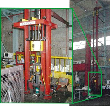
- High-tensile steel is used for frame members of cars, and there are the member to which high energy absorption capacity is notably requested, such as the front side rail, and the member to which protection of crew from collision is requested, such as the B pillar. For the evaluation of these members, it is necessary to obtain the collision absorption energy generated at collision and the deformation characteristics. To this end, tests are executed in accordance with purposes, from the high-speed tensile test at the level of test specimens to the high-speed crush test for actual components. For the high-speed tensile test machines at the level of test specimens, there are the hydraulic servo type test machine, Hopkinson bar test machine, one-bar test machine and gauging base type test machine, etc. Further, various test machines are devised for the component crush test machine. As the one example, Fig.6 shows the outline of the high-speed impact test machine in which a weight of 200 kg is run into a tested object at a collision speed of 50 km/h. Measurement of the deformed state of the tested object with a high-speed camera, measurement of the deformation load with a load cell and measurement of crush energy have been executed.
Figure 6Outline and external view of the high-speed crush test machine
- 3-3. Evaluation of delayed fracture
- The problem of delayed fracture became obvious with high-tensile bolts, and study of the evaluation method for bolts went ahead. After that, the high-tensile steel exceeding the 980 MPa class has been also used for steel sheets, and the problem of delayed fracture has become to draw attention. Since the unified evaluation method for delayed fracture is not yet established, respective iron and steel companies and automobile companies are presently evaluating by their own way of thinking and methods.
Since delayed fracture of steel sheets relates to three elements, i.e., the strain introduced by press work, applied stresses, and amount of penetrated hydrogen, it is necessary to carry out the test considering these elements. It is the most real method to evaluate the components to be tested under the environment of actual use. However, it is actually impossible and in general, the components are simulated, and evaluated under the test conditions of accelerated environment. For example, a component is processed in such a manner which is most similar to the severest processing part of the component by bending work, then the stress is added which simulates the stress applied at tightening the component, hydrogen is introduced at inside the thinned HCl solvent or by means of the cathode charging method, and thus the test is executed.
It is considered that evaluation of delayed fracture should be totally judged by the combination of the macroscopic test that has simulated the actual shapes of components and environment as far as possible, with the academic evaluation for analyzing the difference. The Kobelco Research Institute, Inc. is provided with the test equipment which can cope with any test method, and at the same time, it has been executing the comprehensive evaluation by measurement of diffusible, nondiffusible hydrogen amount with the API-MS (Atmospheric Pressure Ionization-Mass Spectrometer) and by observation of the fractured surfaces on the rupture test specimens with SEM.
- 3-4. Weldability, fatigue characteristics
- Spot welding, arc welding and laser welding are used for junction of car components. When using high-tensile steel sheet, welding defect tends to be generated because the amounts of carbon and various alloy elements are high. Further, in the steel sheets strengthened by the structure such as martensite, softening occurs at heat-affected zones, and fracture originated from the softened part and/or lowering of fatigue characteristics may be generated. In order to grasp these situations, a series of test evaluations have been executed such as for the welding test, strength test and fatigue test.
- Conclusion
- Recent outline of the high-tensile steel for automobiles and its evaluation technologies have been introduced. Material and processing technologies are both progressing daily, and the newest equipment as well as upgrading of technologies is always requested also to the evaluation technologies imposed on our company. We think that requests from various users are the strongest power to promote the technology development. So, please contact us. (Thank you for your attention.)
Examination & research example
- Automotive
- Automotive Durability Evaluation Technology ~ 4-Poster Testing~
- Automotive Durability Evaluation Technology ~Durability Test and Measurement Technology ~
- Evaluation Technologies on High Strength Steel Sheet Atmospherefor Automobiles
- Safety Evaluation Test of On-board Lithium-ion Battery
- Techniques for Evaluation of Applicability of Biofuels